

1. Determine Load Characteristics
Load Type: Rotary load (e.g., turntable) or linear load (e.g., lead screw).
Load Inertia (J_load):
Calculate the load's moment of inertia (this can be computed using CAD software or standard formulas).
The Inertia Ratio (Load Inertia / Motor Rotor Inertia) is a critical metric:
General Machinery: Recommended ≤ 5:1
High Dynamic Response (e.g., Robotics): ≤ 3:1
Precision Positioning (e.g., Semiconductor Equipment): ≤ 1:1
Frictional Resistance: Measure or estimate the friction force of the guide rails or gears (T_friction).

2. Analyze the Motion Profile
Motion Trajectory: Plot the velocity-time (or angle-time) curve.
Key Parameters:
Maximum Velocity (v_max)
Acceleration/Deceleration (a)
Acceleration/Deceleration Time (t_acc, t_dec)
Run Time vs. Dwell Time (Duty Cycle).
Sample Calculations:
Acceleration Torque: T_acc = J_total × α (where α is angular acceleration; α = Δω / t_acc)
Constant-Speed Torque: T_const = T_friction + T_external (e.g., cutting force)
Deceleration Torque: T_dec = J_total × α - T_friction
3. Calculate Key Torque Values
Peak Torque (T_peak):
T_peak = max(T_acc, T_const, T_dec)
This value must be less than the motor's peak torque (typically 2 to 3 times the rated torque).
RMS Torque (T_rms):
T_rms = √[(T_acc²·t_acc + T_const²·t_const + T_dec²·t_dec) / (t_acc + t_const + t_dec + t_idle)]
This value must be less than the motor's rated torque.

4. Determine Speed Requirements
Maximum Speed (N_max) must be lower than the motor's rated speed (note the torque derating that occurs at high speeds).
Overload Capacity Verification: At N_max, verify whether the required torque falls within the motor's operating region.

5. Selecting the Motor Type
Rotary Motors:
Low-Inertia Motors: High responsiveness (e.g., robotics).
High-Inertia Motors: Stability under heavy loads (e.g., machine tool feed axes).
Linear Motors: Require specialized drives (no mechanical transmission chain; high precision).
Key Parameter Matching:
Motor Rated Torque ≥ T_rms
Motor Peak Torque ≥ T_peak
Rated Speed ≥ N_max

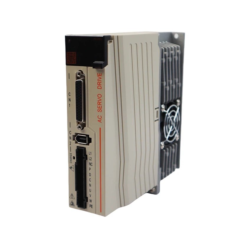
6. Key Parameters for Drive Selection
Output Current Capability:
Continuous Current > Motor Rated Current
Peak Current > Motor Peak Current (typically designed with a 150%–200% overload margin).
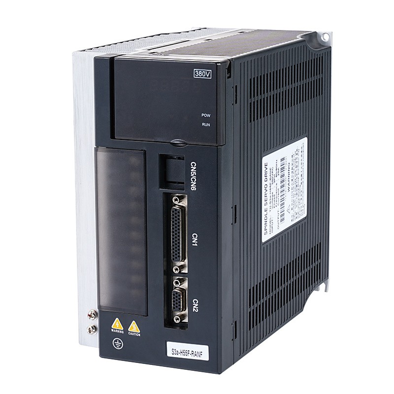
Voltage Matching:
Input Voltage (Single-phase 220V / Three-phase 380V) must match the power grid supply.
DC Bus Voltage must be sufficient to accommodate the motor's back EMF (especially at high speeds).
Regenerative Energy Handling:
Built-in braking resistor? Calculation for external resistor power rating:
P_resistor = (J_total × ω²) / (2 × t_dec)
For high-inertia systems or applications involving frequent starts/stops, a regenerative energy feedback unit should be selected.

7. Functional and Interface Requirements
Control Modes:
Position Control (Pulse / Fieldbus)
Speed Control (Analog Input)
Torque Control (e.g., winding applications).
Feedback System:
Encoder Type (Incremental / Absolute) and Resolution (17-bit or higher for precision positioning).
Support for Dual Encoders (for full closed-loop control).
Communication Bus:
EtherCAT, CANopen, PROFINET, etc.; must be compatible with the upstream PLC protocol.
Safety Functions:
STO (Safe Torque Off) compliant with SIL3 / PLe safety integrity levels.

8. Environmental Suitability
Protection Class (IP Rating): IP20 (for cabinet installation) or IP65 (for installation without a protective cabinet).
Temperature Range: Industrial Grade (-10°C to 50°C); derating may be required for high-temperature environments.
Vibration / Shock: Compliant with IEC 60068-2-6 standards (e.g., vibration >5g may require reinforced mounting).
9. System Integration Verification
Simulation Software: Use the selection tools provided by the manufacturer (e.g., Siemens Sizer, Yaskawa SigmaSize+) to verify dynamic performance.
Electrical Compatibility:
Drive-to-Motor Cable Length: (Output reactors are required for long cable runs).
EMC Filters: (Must comply with the IEC 61800-3 standard).
Thermal Design: Calculate power loss (P_loss ≈ Drive Efficiency × I²), and ensure adequate space for heat dissipation.

10. Brand and Service
Technical Support: Does the manufacturer provide parameter tuning services?
Spare Parts Availability: For critical industries (e.g., medical equipment), a guaranteed supply of spare parts for 10 years or more is required.
Cost Optimization: Provided that performance requirements are met, compare the total lifecycle costs (including energy consumption).
Selection Considerations
Safety Margins: For torque and speed, it is recommended to reserve a margin of 15%–20% to accommodate unforeseen load variations.
Third-Party Compatibility: When mixing brands, verify that the motor encoder protocol is compatible with the drive (e.g., Hiperface DSL, BiSS-C).
Harmonic Suppression: High-power drives (>5 kW) require the installation of input reactors to mitigate grid harmonics.
Dynamic Stiffness: For high-precision positioning applications, pay close attention to speed loop and position loop gains, and select a drive with high dynamic response capabilities.

Final Checklist:
Inertia ratio falls within a reasonable range.
T_rms < Motor Rated Torque.
T_peak < Motor Peak Torque.
Encoder resolution meets the required positioning accuracy.
Regenerative energy handling solution is comprehensive and adequate.
By following the steps outlined above, common issues-such as overload alarms, positioning jitter, or thermal shutdowns-can be avoided. It is recommended to collaborate with the supplier's technical team to verify the selected solution, particularly in new application scenarios.