

T3a/T3L Series
T3a/T3L series digital AC servo drive is independently developed and produced by Zhejiang Tonghang Electric Drive Technology Co., Ltd. It is a general AC servo drive product with leading domestic level. This series of products adopts advanced full digital control and AC motor vector control theory, with excellent system performance and high reliability, and is widely used in servo axis drive of food processing, packaging machinery, textile machinery and other related automation industry machinery.
T3a/T3L series Product features
Driver command type is pulse type, motor position feedback is pulse incremental encoder
Adopt high-performance main control chip, excellent control performance
T3a series fully sealed design, good protection, strong anti-interference ability
T3L series compact design, saving installation space
Select new industrial-grade IPM module, strong overload drive capability
Integrate position control, speed control, torque control
Can drive various types of permanent magnet synchronous servo motors
Equipped with comprehensive fault protection and statusmonitoring functions
Has excellent low-speed torque characteristics and dynamicacceleration and deceleration performance

Driver Model Specifications and Functions
|
Model |
T3x-L20 |
T3x-L30 |
T3x-L40 |
T3x-L50 |
T3x-L75 |
T3x-H25 |
T3x-H50 |
T3x-H75 |
||
|
Input Power Supply |
Main power Supply |
Single phase/Three phase 220VAC -15%+10% 50/60Hz |
3-phase 380VAC -15%+10% 50/60Hz |
|||||||
|
Environment |
Temperature |
Work:0℃~40℃ Storage:-40℃~50℃ |
||||||||
|
Humidity |
Job:40% ~ 80%( no condensation) Storage:less than 93%(no condensation) |
|||||||||
|
Atmospheric pressure |
86kPa ~ 106 kPa |
|||||||||
|
Protection Level |
IP20 |
|||||||||
|
Control Mode |
position, speed, torque, position/speed, speed/torque, position/torque |
|||||||||
|
Digital Input |
6 programmable input terminals (optically isolation) |
|||||||||
|
Digital Output |
4 programmable output terminals (photoelectric isolation) |
|||||||||
| Communication method | Rs485 communication | |||||||||
|
Encoder Signal output |
signal type |
A, B, Z differential output, Z signal open collector output |
||||||||
|
Position |
Input frequency |
Differential input: ≤500kHz (kpps); Single ended input: ≤200kHz (kpps) |
||||||||
|
Command mode |
Pulse + Direction; Forward/Reverse Pulse; Orthogonal Pulse |
|||||||||
|
Electronic gear ratio |
1~32767/1 ~ 32767 |
|||||||||
|
Speed |
Simulate command input |
±10VDC, input impedance 10kΩ |
||||||||
| Command acceleration and deceleration |
Parameter setting P-060/P-061 |
|||||||||
|
Instruction source |
Analog quantity,internal speed command | |||||||||
|
Torque |
Simulate command input |
-10V ~ +10V, input impedance 10kΩ |
||||||||
|
Torque limit |
Parameter setting P-065/P-066 |
|||||||||
| Instruction source | Analog quantity,internal torque command | |||||||||
|
Monitoring function |
Overspeed,overvoltage,overcurrent,overload,abnormal braking,abnorma lencoder,position deviation,instruction overclocking, etc. |
|||||||||
| Protection function |
Overspeed, overvoltage, overcurrent, overload, abnormal braking, abnormal encoder, position deviation, instruction overclocking, etc. |
|||||||||
|
Characteristic
|
Speed frequency response |
≥800Hz |
||||||||
| Speed fluctuation rate |
<±0.03% (load 0~100%); <±0.02% (power supply -15%~+10%) |
|||||||||
Servo drive model specification

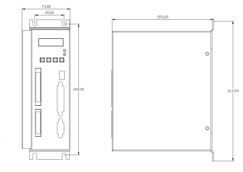
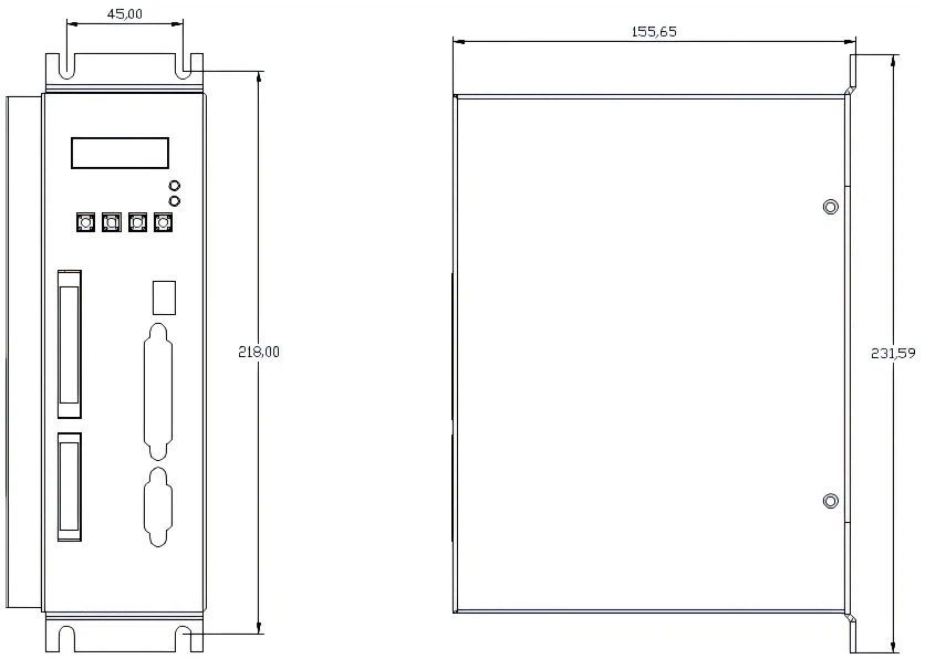
T3a Series Servo Drive External Dimensions(mm)

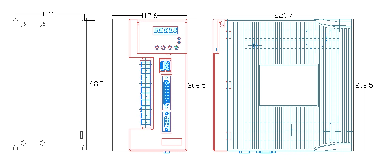
T3L Series Servo Drive External Dimensions(mm)


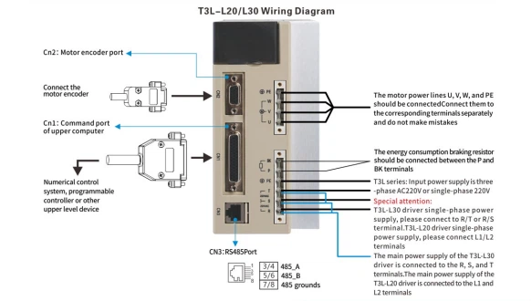
T3L Servo Drive Wiring Diagram
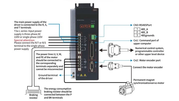
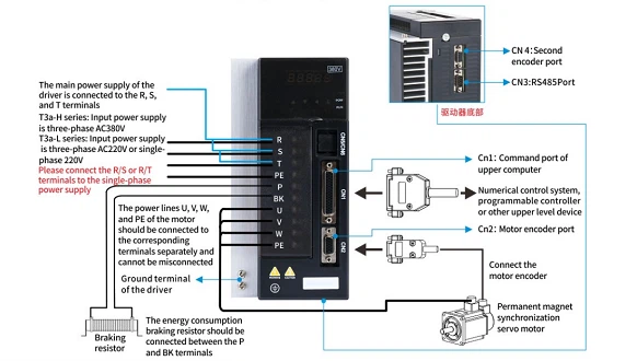
Controlwiring Diagram

Special attention:
lf the pulse command signal is a 24V power supply, PULS+must be connected to pin 39 of CN1, andSlGN+must be connected to pin 38 of CN1, otherwise it may damage the pulse command port;
lf the pulse commandsignal is a 5V power supply, PULS+must be connected to pin 25 of cN1, and SiGN+must be connected to pin 24 of CN1.otherwisethere may be abnormal pulse reception;
Introduction To Servo Drive Ports
|
Name |
Symbol of terminal |
Detailed description |
| Main circuit power supply | R, S, T or L1, L2 (T3L-L20) | Connect to external AC power supply; Three-phase AC220V (85%~110%) 50/60Hz Single-phase/three-phase AC220V (85%~110%) 50/60Hz |
| Braking resistor terminal |
P,BK |
When using an external braking resistor in parallel with an internal braking resistor, pleasepay attention to selecting the resistance and power to avoid burning out the driver. |
|
Motor connection terminal |
U |
Output to motor U phase power supply |
|
V |
Output to motor V phase power supply |
|
|
W |
Output to motor W phase power supply |
|
|
Terminal of ground
|
|
Grounding terminal of motor casing |
|
or PE |
Driver grounding terminal |

Control Circuit Terminal
| Type | Name | Function | Detailed Description |
|---|---|---|---|
| External 24V control power supply | COM+ | DC24V control power output terminal | The positive pole of the power supply at the input terminal is used to drive the optocoupler at the input terminal, DC12~24V, Current ≥100mA. Power ground of input terminal |
| DO (COM) | Control power input terminal | - | |
| Control signal input (programmable) | DI1(SON) | Enable input | DI1 - DI6 digital input functions are all programmable. The examples shown in this table are factory default configurations, which can be flexibly configured by driver software parameters and can be adapted to various types of upper computers, such as CNC systems, PLC, Motion controllers, etc. |
| DI2(ACLR) | Alarm clearing | ||
| DI3(CCWL) | CCW drive prohibited | ||
| DI4(CWL) | CW drive prohibited | ||
| DI5(CLE) | Zero position deviation | ||
| DI6 | custom | ||
| Control signal output(programmable) | DO1(RDY) | Servo ready | All DO1 - DO4 digital output functions are programmable, and the examples shown in this table are factory default configurations. They can be flexibly configured by driver software parameters and can be adapted to various types of upper computers, such as CNC systems PLC, Motion controllers, etc. |
| DO2(ALM) | Alarm output | ||
| DO3(COIN) | Positioning completed | ||
| DO4(BRK) | Brake output | ||
| Analog command input | AS+ | Simulate command input positive | Positive connection with the analog command output of the upper computer |
| AS- | Simulate instruction input negative | Negative connection to the analog command output of the upper computer | |
| GNDA | Analog signal ground | Connect to the analog signal ground of the upper computer | |
| Pulse quantity command input |
PULS+ | Command pulse PLUS input | External command pulse input terminal. Note: The pulse input mode is set by parameter P035 and supports three types of pulse input modes ◆P035-0: Command pulse+direction mode (default state); ◆P035-1: CCW/CW (instruction pulse mode); ◆P035-2:Orthogonal pulse mode. |
| PULS− | |||
| SIGN+ | Command pulse PLUS input | ||
| SIGN− | |||
| Encoder output signal (sent to the upper computer) |
OA+ / OA- | Encoder A-phase signal output | ◆Encoder ABZ signal differential drive output (26LS31 output, equivalent to Rs422); ◆Non isolated output (non insulated). |
| OB+ / OB- | Encoder B-phase signal output | ||
| OZ+ / OZ- | Encoder Z-phase signal output | ||
| CZ | Encoder Z-phase collector electrode open circuit output | ◆The Z-phase signal of the encoder is output by an open collector. ◆When the Z-phase signal of the encoder is outputs, it outputs ON (output conduction), otherwise it outputs OFF (output cutoff); (non isolated output/non insulated); |
|
| GND | Encoder signal ground | ||
| Encoder input signal (from spindle motor) |
A+/A- | Encoder A-phase signal input | Servo motor encoder signal input terminal, different types of encoder signals have different definitions. The table shows the photoelectric encoder, and subsequent products support photoelectric encoders, rotary encoders, sine cosine encoders, and absolute value encoders. |
| B+/B- | Encoder B-phase signal input | ||
| Z+/Z- | Encoder Z-phase signal input | ||
| U+/U- | Encoder U-phase signal input | ||
| V+/V- | Encoder V-phase signal input | ||
| W+/W- | Encoder W-phase signal input | ||
| 5V/GNDD | Encoder 5V power/groud | ||
| Grounding terminal | PE / FG | Shielded wire protection ground | Connect to the shielded wire of the signal cable |
Driveracce ssories(braking Resistor)
T3a - H series (380V servo) brake resistor configuration table (standard 380V servo does not include built - in resistors, external brake resistors must be connected, except for customized models)
| Drive Model | (Light load type) Recommended configuration (infrequent start stop) | (Heavy duty type) Recommended configuration (frequent start stop) |
|---|---|---|
| T3a - H25F | ≥ 50 ohms, power greater than 1000W | ≥ 50 ohms, power greater than 1500W |
| T3a - H50F | ≥ 50 ohms, power greater than 1000W | ≥ 50 ohms, power greater than 1500W |
| T3a - H75F | ≥ 30 ohms, power greater than 1500W | ≥ 30 ohms, power greater than 2000W |
T3a - L/T3L series (220V servo) brake resistor configuration table (standard 220V servo includes built - in resistor, external brake resistor can be selected according to load conditions)
| Drive Model | (Light load type) Recommended configuration (using built-in resistor) | (Heavy duty type) Recommended configuration (with external resistor connected in parallel) |
|---|---|---|
| T3a/T3L-L20F | 47 euros (built-in) | ≥ 47 euros, 500W |
| T3a/T3L-L30F | 47 euros (built-in) | ≥ 47 euros, 500W |
| T3a-L40F | 47 euros (built-in) | ≥ 47 euros, 500W |
| T3a-L50F | 47 euros (built-in) | ≥ 47 euros, 500W |
| T3a-L75F | 47 euros (built-in) | ≥ 20 euros, 1000W |
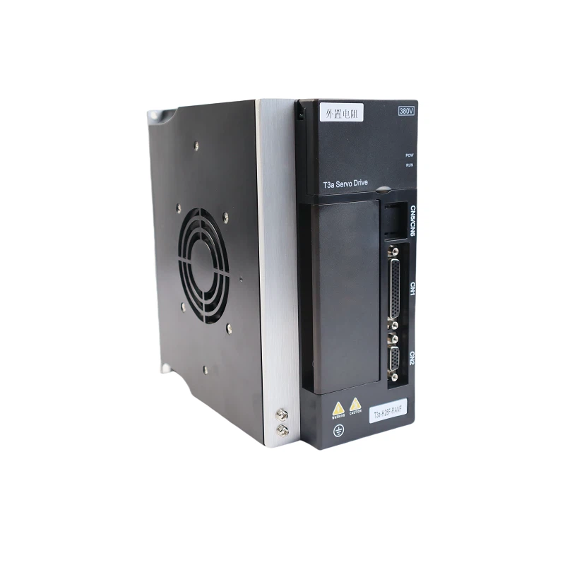
TH-T3a-H25F-RANF


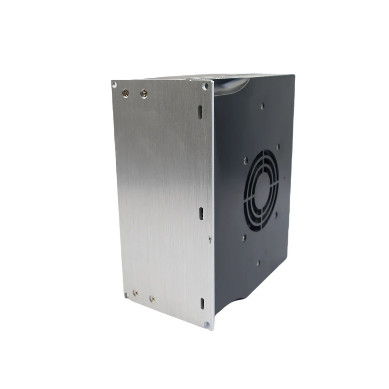


TH-T3a-L30F-RABF


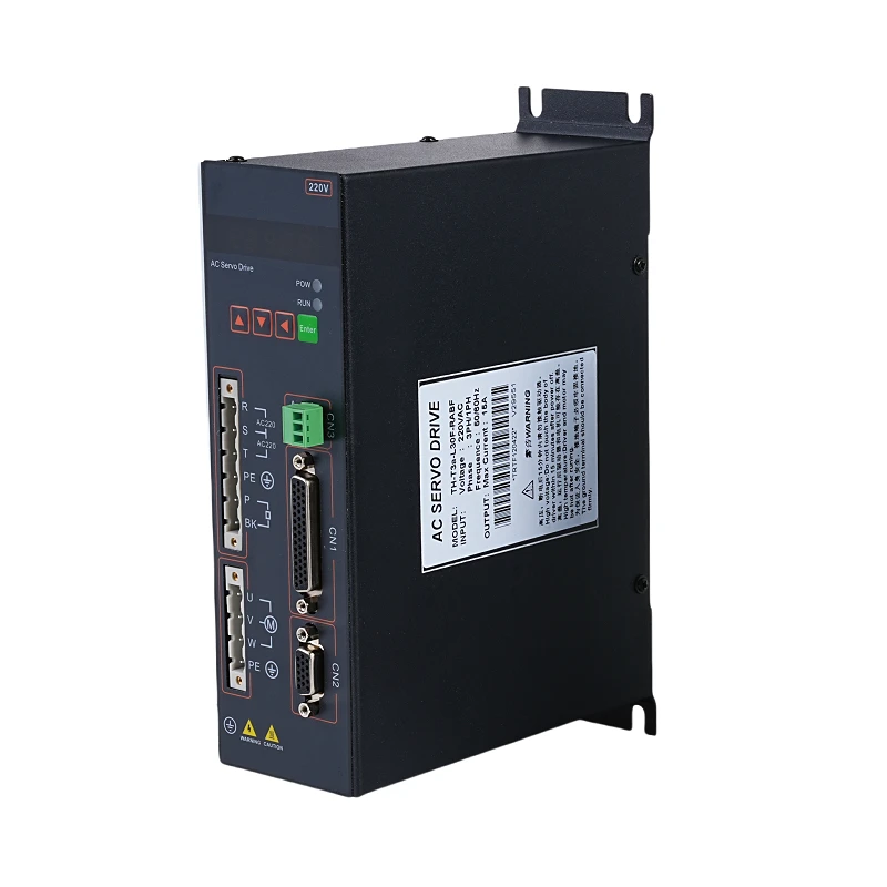


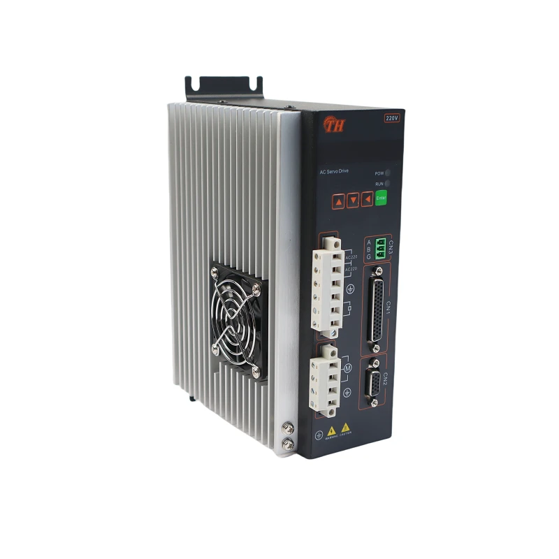

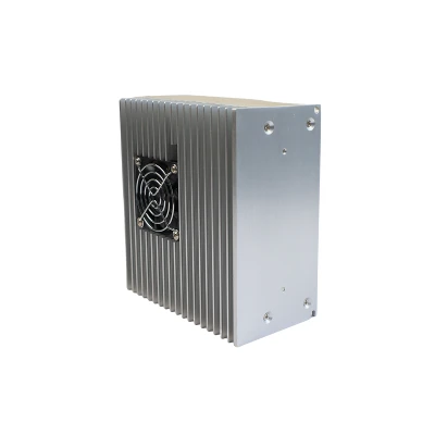
TH-T3L-L30F-GABF


TH-T3L-L30F-RABF

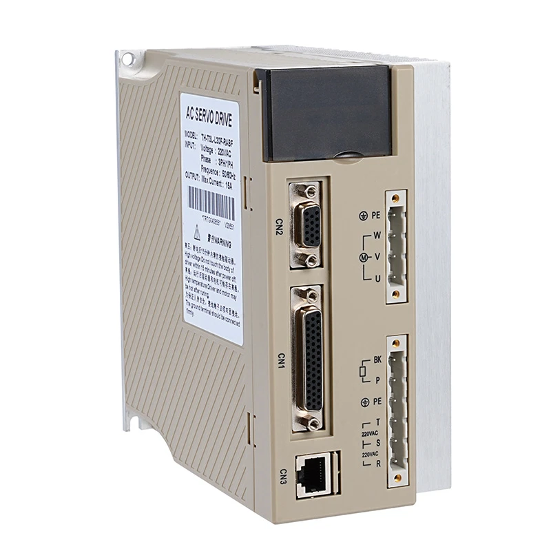


As one of the leading t3a/t3l series drives manufacturers and suppliers in China, we warmly welcome you to buy the best t3a/t3l series drives at competitive price from our factory. For more company information, contact us now.